Inovus support centre
Hardware setup
Bozzini Hysteroscopy Simulator Setup Manual
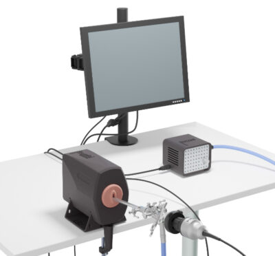
Welcome to the step-by-step assembly guide for the Bozzini Hysteroscopy Simulator. Whether you prefer step by step instructions or a video demonstration, this guide will walk you through the assembly process.
Before you begin, take a moment to review the package's contents and acquaint yourself with the included components. The following content has been crafted to provide you with all the insights required to transform individual parts into a functional and invaluable tool for honing your surgical skills.
Step-by-Step guide
Let's start assembling and enhancing your surgical skills, one step at a time.
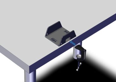
Step 1
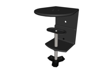
Begin by placing the U-shaped bracket on a suitable flat surface. Then, place the top portion of the small clamp through the opening at the front of the bracket, as illustrated here.
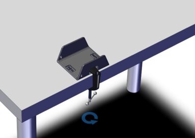
Step 2
Once in position, turn the handle until the clamp grips firmly to the bracket and flat surface.
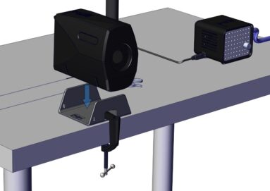
Step 3
Place the retaining case onto the U-shaped bracket as shown.
Step 4
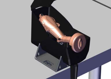
The set-up should now look similar to this image.
Step 5
You are now ready to place a uterus model inside the case. Hook the loops of the model onto the internal fixings so that it is held securely in place.
Step 6
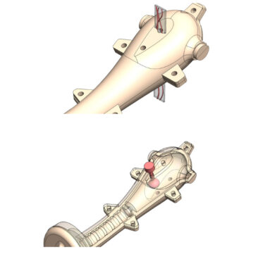
At this stage you may introduce pathologies into the uterus, if your selected model allows you to do so.
Adhesions are inserted by placing the thread through one of the top holes and then pulling it through the corresponding hole below.
Polyps are inserted in the same way, however they do not need to be pulled all the way through the uterus.
Step 7
You are now ready to assemble the monitor bracket. Begin by removing the C-clamp from the package.
If your simulator was purchased in a hard shell carry case, the monitor bracket will be assembled already and you may skip to Step 15.
Step 8
Using the three black bolts provided, attach the black post to the C-clamp.
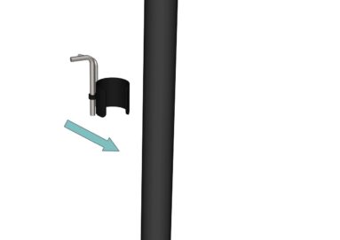
Step 9
Just so that we know where they are for later, identify the two Allen keys along with the push fit clamp provided. Snap this to the post and move to the next step.
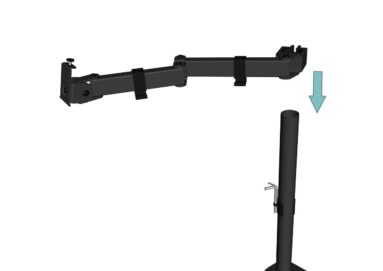
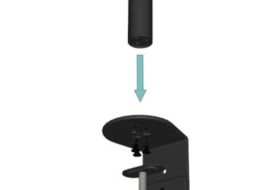
Step 10
The swivel arm should be pre- assembled. Slide this onto the black post, then move to the next step.
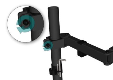
Step 11
At the desired height, use the largest Allen key to lock into position by turning the bolt in a clockwise direction. Once this step is complete, you may insert the end cap.
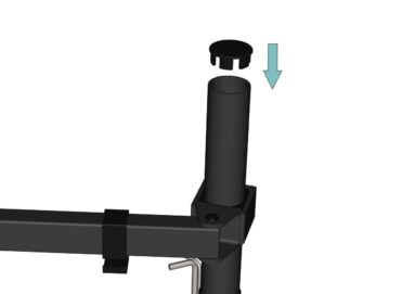
Step 12
Push the end cap into position.
Step 13
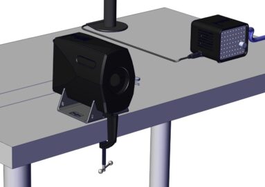
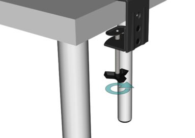
With the bracket fully assembled, anchor it to your chosen work surface by turning the handle until it is tight.
Step 14
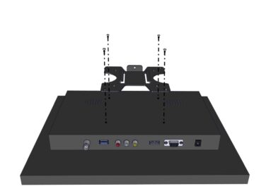
Take the screen bracket and screw this to the back of the monitor using the bolts provided.
Step 15
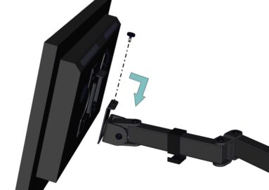
Slide the monitor into position and screw the bolt into place.
Step 16
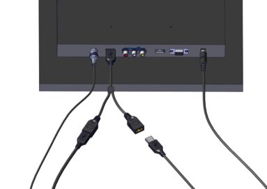
All wiring can be completed using the numbered stickers attached to the ends of each adapter.
For additional support, use this visual guide.
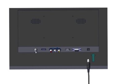
Start by plugging in the 12V power adapter.
Step 17
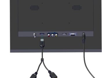
Connect the USB splitter to the rear of the monitor as shown.
Step 18
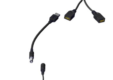
Connect the USB to 5V adapter to one of the USB ports. Connect the female end of the BNC cable to the male end of the 5V adapter.
Step 19
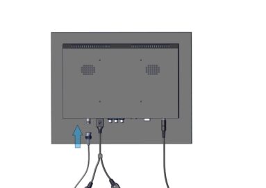
Connect the female end of the BNC extender to the screen.
Step 20
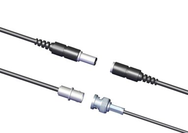
Locate the endoscopic camera in the package. Connect the opposing ends of the BNC cable to the camera connectors.
Step 21
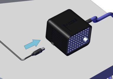
Connect the USBA/B cable to the remaining USB port on the USB splitter.
Step 22
Now connect this wire to the bozzini light source.
Step 23
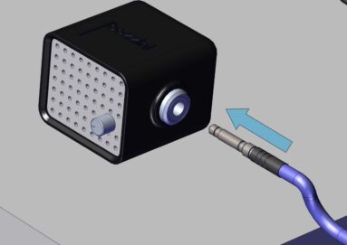
Plug in the male end of the fibre-optic cable into the light source.
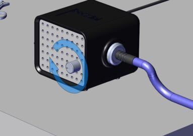
Step 24
When the screen is powered on, you should be able to turn the knob on the front of the light source to activate the light. Test the light at this stage and switch off.
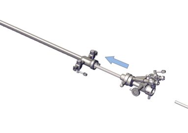
Step 25
Remove the introducer from the packaging. Ensure the introducer is placed inside of the sheath as illustrated here. In most cases, this step will already have been completed for you.
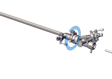
Step 26
Rotate the latch in a clockwise direction to ensure the two components are securely connected.
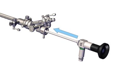
Step 27
You are now ready to insert the scope into the introducer. Once the scope is fully inside, ensure it is locked in place using the latch.
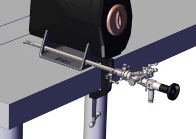
Step 28
You may use the apertures in the U-shaped bracket to hold the assembly in place as shown here.
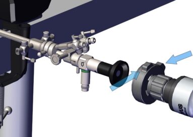
Step 29
Connect the endoscopic camera to the scope by pinching the two clasps as shown here.
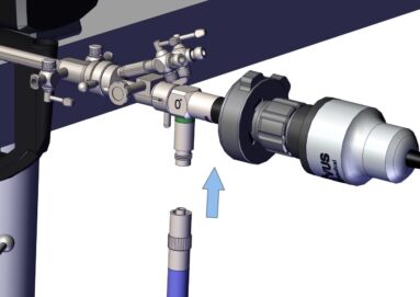
Step 30
Attach the other end of the fibre-optic cable to the connector on the scope by screwing it into place.
At this stage, you are ready to turn the light source on.
Assembly Video
View the assembly video for the Bozzini Hysteroscopy Simulator
Downloads
You can save the Bozzini Hysteroscopy Simulator Setup Manual below. Or print this page for a hard copy version.
Was this article helpful?
We’re sorry to hear that.
Please can you give us some feedback to improve this page?
If you’d like a member of our support team to get back to you, please send a message to support@inovus.org