Inovus support centre
Hardware setup
HystAR Pro Setup Manual (1st Generation)
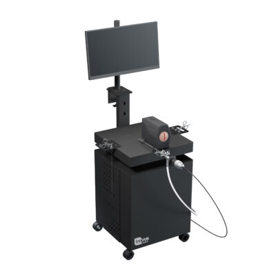
Welcome to the step-by-step assembly guide for the HystAR Pro. Whether you prefer step by step instructions or a video demonstration, this guide will walk you through the assembly process.
Before you begin, take a moment to review the package's contents and acquaint yourself with the included components. The following content has been crafted to provide you with all the insights required to transform individual parts into a functional and invaluable tool for honing your surgical skills.
Step-by-Step guide
Let's start assembling and enhancing your surgical skills, one step at a time.
Step 1
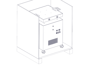
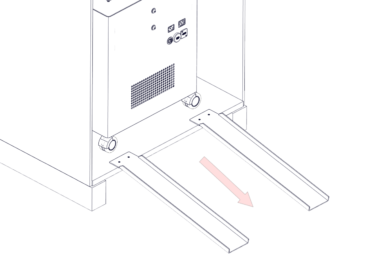
On opening the crate locate the two metal ramps.
Step 2
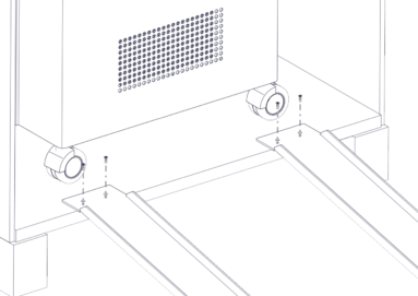
Align the ramps with the trolley wheels.
Step 3
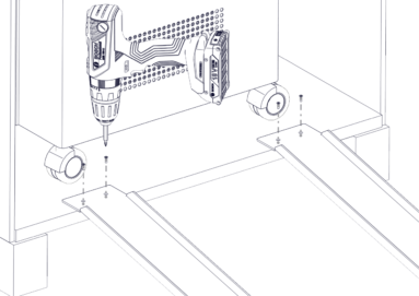
Attach the ramps to the inside of the base of the crate with the screws provided as shown.
Step 4
Manouvre the trolley onto the ramps ensuring the wheels are pointing in a forward position and roll the trolley down the ramps and onto a level surface.
Step 5
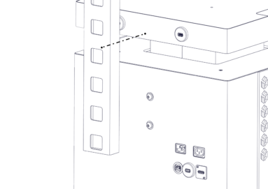
Start the assembly of your portable trolley system by unscrewing the M8 bolts at the rear of chassis so that you have around 3-4mm of space between the head of the bolt and the chassis wall.
You can do this using the allen key provided.
Step 6
Take the L shaped screen bracket and place it onto the M8 bolts as shown.
Drop the bracket onto the bolts.
Step 7
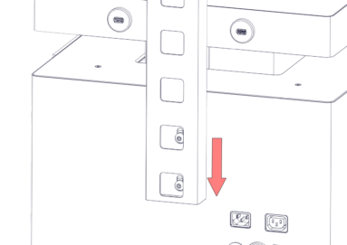
Screw the bolts tight using the allen key provided.
Be careful not to overtighten at this stage.
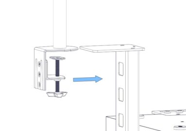
Step 8
Take the assembled monitor bracket and clamp it in position as shown.
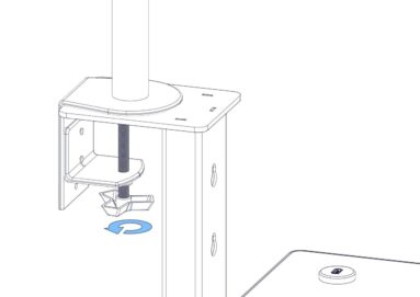
Step 9
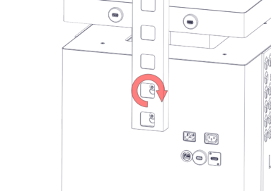
Screw the clamp clockwise until tight.

Step 10
Attach the monitor screen using the 4 x M5 bolts provided.
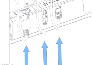
Step 11
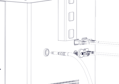
As shown in the image, plug in the IEC, HDMI & USB cables.
Step 12
Carefully thread the 3 wires we plugged in during the previous step up through the L shaped bracket and onto the monitor bracket. Move to the next step.
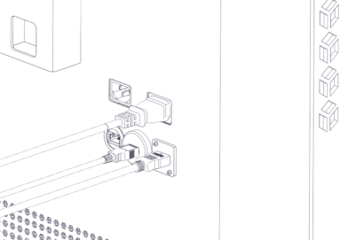
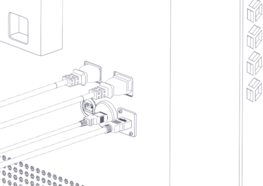
Step 13
Position the wires as such and plug in to the appropriate socket.
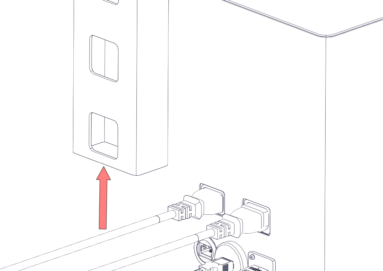
Step 14
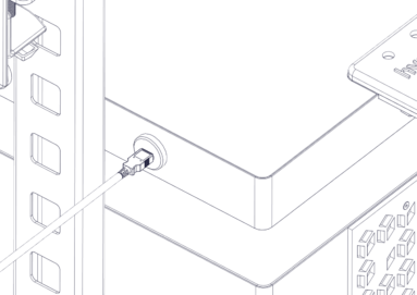
Plug the IEC connector into the back of the system.
Step 15
Align the U-shaped bracket with the bolt holes on the top of the trolley system and screw in position.
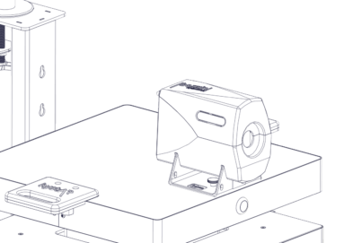
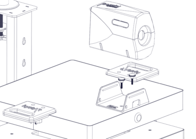
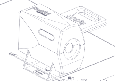
Step 16
You may now place the uterus housing onto the U-shaped bracket.
Please note this is a push fit fixture.
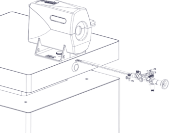
Step 17
Insert the scope into the introducer.
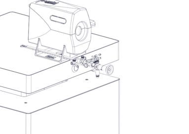
Step 18
Place the hysterscope in the holes provided on the left hand side of the U-shaped bracket.
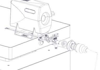
Step 19
Taking the camera attach the coupler to the scope.
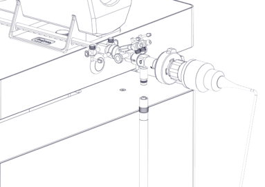
Step 20
Screw the fibre optic light lead to the scope as shown.
Step 21
Insert the fibre optic light lead into the back of the trolley system.
Step 22
Plug in the USB cable to the USB ports on the trolley system
Step 23
Turn the system on using the power switch on the front of the trolley system.
Once the computer has loaded up, select the HystAR icon on the monitor and follow the instructions inside the software.
Assembly Video
View the animated assembly video for the Hyst AR Pro
Downloads
You can save the HystAR Pro setup manual below. Or print this page for a hard copy version.
Was this article helpful?
We’re sorry to hear that.
Please can you give us some feedback to improve this page?
If you’d like a member of our support team to get back to you, please send a message to support@inovus.org