Inovus support centre
Hardware setup
Pyxus HD Move Setup Manual
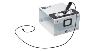
Welcome to the step-by-step assembly guide for the Pyxus HD Move. Whether you prefer step by step instructions or a video demonstration, this guide will walk you through the assembly process.
Before you begin, take a moment to review the package's contents and acquaint yourself with the included components. The following content has been crafted to provide you with all the insights required to transform individual parts into a functional and invaluable tool for honing your surgical skills.
Step-by-Step guide
Let's start assembling and enhancing your surgical skills, one step at a time.
Step 1
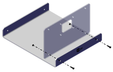
Begin the assembly by taking out parts 00000917 and 00000328. Using 2 x 00000640 bolts and 2 x 00001159 nuts, screw the 00000328 panel into position as shown.
Step 2
You will now need the following parts:
- 00000340
- 00000339
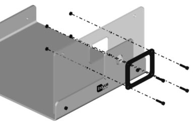
Using the 00000640 bolts and 4 x 00001159 nuts, secure the white skin and black bracket to the 00000328 panel.
Please note that the black bracket must be placed on the outside of the white skin as shown in the image.
Step 3
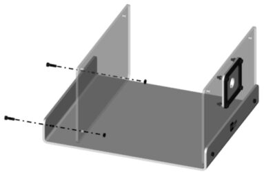
Using 2 x 00000640 bolts and 2 x 00001159 nuts, secure the rear panel 00001457.
Step 4
Your simulator should now look like this, with both upright panels securely in position.
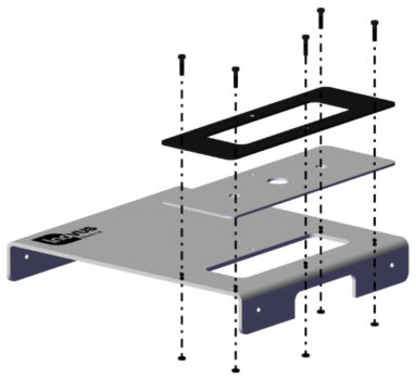
Step 5
You may now start the top panel sub-assembly. Taking 00001201, 00000170 and 00000171, secure as shown using 5 x 00000640 bolts and 5 x 00001159nuts.
For the moment, leave the rear centre hole free.
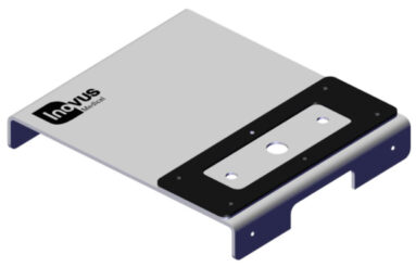
Step 6
You have now completed the top panel sub-assembly.
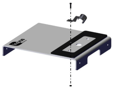
Step 7
Use the remaining 00000640 bolt and
1 x 00001159 nut to position the camera bracket (00000338).
Step 8
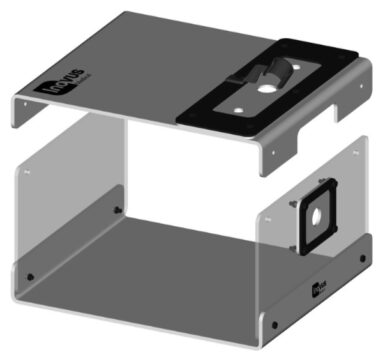
Having already completed the
top panel sub-assembly, you may now position it over the pre-assembled base unit.
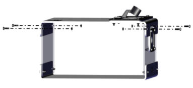
Step 9
Using 2 x 00000640 bolts & 2 x 00001159 nuts, secure it to the upright panels.
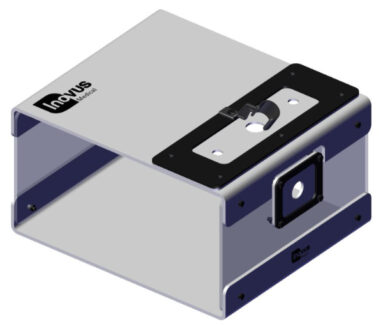
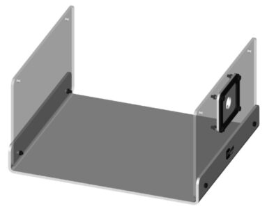
Step 10
Your simulator should now look like this and be structurally sound.
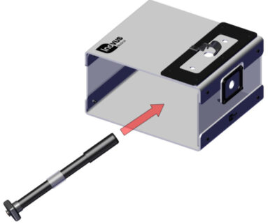
Step 11
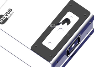
You may now position the scope to begin training. The scope must be placed backwards through the ports, as illustrated. Positioning the scope in this way reduces the risk of skin tearing.
Please note you will need to thread the scope wire through the chosen port first.
Step 12
You may wish to rotate the camera bracket to one side so that the scope has room to slide into position.
Step 13
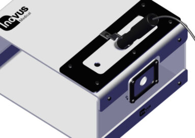
You may now rotate the camera bracket back into position to hold the scope in place.
The bracket is designed for solo training and may be removed for the purpose of training camera operators.
Step 14
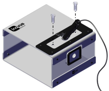
Insert the two trocars provided into the openings in the SK04 skin. Using the trocars will reduce the likelihood of the skin tearing.
Step 15
Please note that the scope may be placed in the front port also.
This will require a camera operator in most cases.
Step 16
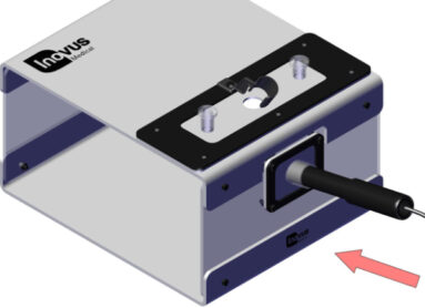
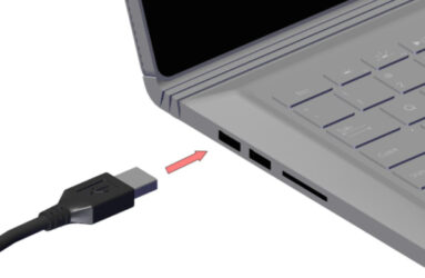
Connect the USB cable provided to your laptop or PC. (Laptop not included)
Step 17
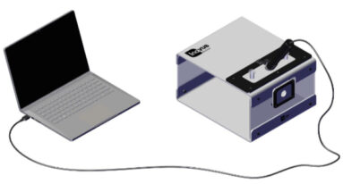
The setup should now look similar to this image.
The lights on the scope should now be illuminated.
You should now be ready to start training. Should you have any problems during setup or something isn’t quite working as you’d expected, please contact us at info@inovus.org or call 01744 752 952 to speak with an adviser.
Opening times are Monday to Friday 9am - 5pm GMT.
Windows 8/10:
To start using your simulator immediately without the need to download software you will need to navigate to the start menu and type “camera” > Click the camera icon or symbol > At this stage your computers default camera may open up, in the event that it does look for the following icon:
![]()
Click it to change the default camera to the simulator camera. Once completed you can now begin to operate.
MAC OS X:
To start using your simulator immediately without the need to download software on your MAC you will need to click the search icon in the top right hand corner of the screen > Type Quick Time > Click the Quick Time icon > Once ready you should now have the Quick Time options appear in the top left hand corner of the desktop > Click File > New Movie Recording > At this stage the computers default camera may appear on screen > To swap the camera view to the simulator camera you must navigate to the record button:
Click the down arrow the right of the button > Select USB 2.0 Camera. Once completed you can now begin to operate.
Assembly Video
View the assembly video for the Pyxus HD Move
Downloads
You can save the Pyxus HD Move setup manual below. Or print this page for a hard copy version.
FAQs
You will need to manually re-focus the camera by twisting the black lens housing. Please note this can be quite stiff. Please see the hardware instructions above for the specific model you have purchased to show you how to do this.
Our LapSkills platform has been discontinued and this is the reason why it is no longer possible for you to login to the site. All of the video resources are available to watch on our YouTube channel.
To operate your simulator, you will now need to use your computer's own software (Mac / Windows) after connecting the simulator's camera.
Please use the buttons below to download the instructions specific to Mac and Windows users.
Was this article helpful?
We’re sorry to hear that.
Please can you give us some feedback to improve this page?
If you’d like a member of our support team to get back to you, please send a message to support@inovus.org