Inovus support centre
Hardware setup
SpineHUB Pro Setup Manual
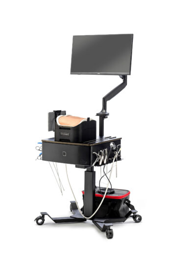
Welcome to the step-by-step assembly guide for the SpineHUB Pro. Whether you prefer step by step instructions or a video demonstration, this guide will walk you through the assembly process.
Before you begin, take a moment to review the package's contents and acquaint yourself with the included components. The following content has been crafted to provide you with all the insights required to transform individual parts into a functional and invaluable tool for honing your surgical skills.
Step-by-Step guide
Let's start assembling and enhancing your surgical skills, one step at a time.
Step 1
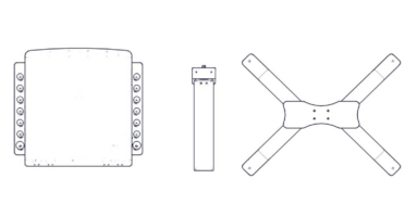
When opening your simulator it
is recommended that you unpack all package contents and arrange them before starting construction.
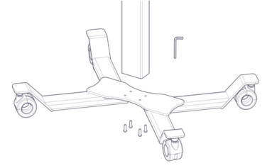
Step 2
Start the assembly of your sim station by screwing the 4x bolts into the underside of the base. You can do this using the allen key provided.
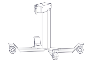
Step 3
Now the base is attached to the main column you are ready to attach the top box.
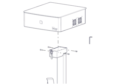
Step 4
Locate the 4x bolts provided to attach the top box.
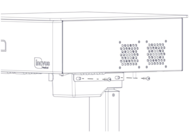
Step 5
Insert two bolts into the side of the
sim station main column and top box, screwing in place with the allen key provided.
Step 6
Ensure the bolts are finger tightened initially whilst you move onto the next step.
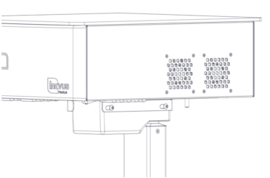
Step 7
Repeat this process on the other side of the sim station.
Step 8
Tighten all screws with allen key provided. The top box should now be securely attached to the main column.
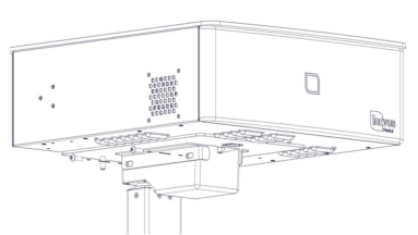
Step 9
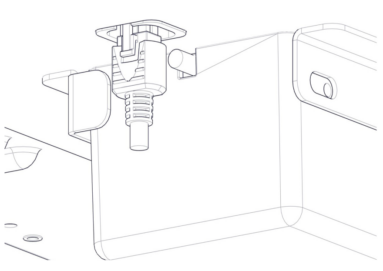
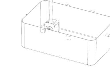
Locate the main column lead on the underside of the sim station box.

Step 10
Secure the lead in place with the connector as shown.
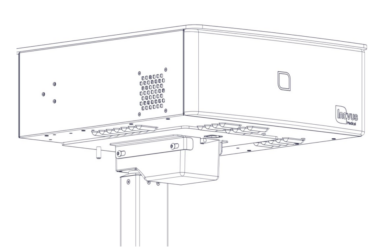
Step 11
Taking the Z-shaped monitor bracket attach to the underside of the top box of the sim station using the 2x nuts provided.
Step 12
Tighten the nuts to ensure the bracket is secured in place.
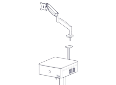
Step 13
Locate the angled tv bracket arm. (There are further instructions included with the monitor arm should you require them).
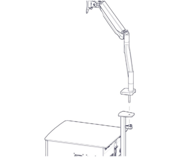
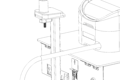
Step 14
Insert the bolt on the base of the the monitor stand into the hole on the top of the Z-shaped bracket now attached to the sim station.
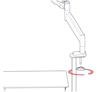
Step 15
Locate the handle and tighten onto the underside of the bolt as indicated.
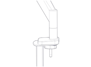
Step 16
Ensure the bolt is tightened.
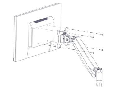
Step 17
Locate 4x bolts and thread through the bracket and into the back of the monitor.
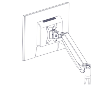
Step 18
Ensure the bolts are securely tightened.
Step 19
Place the LumbarBox Extended sim onto the sim station shelf.
Step 20
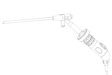
- Attach the camera coupler to the eyepiece of the scope and plug the camera into the back of the sim station.
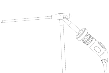
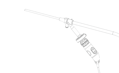
Step 21
- Connect the one end of the fibre optic cable to the endoscope as shown.
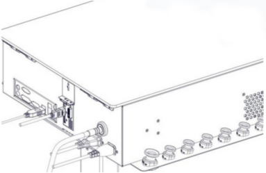
Step 22
Insert the fibre optic cable into the back of the sim station.
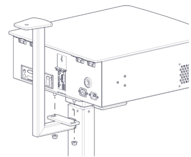
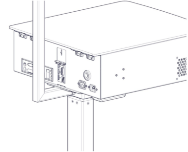
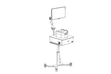
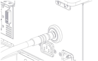
Step 23
Plug the power cables into the relevant ports at the back of the sim station as shown. (Please note the monitor stand is not shown here just for clarity of plug positioning)
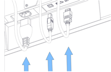
Step 24
Plug the 3 cables into the relevant ports in the underside of the monitor.
Step 25
Connect the Fluid Management System
- Attach the large clear water tube to the rear water inlet port of the Endoscopic LumbarBox Extended.
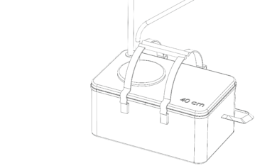
Step 26
Set Up the Water Pump and Water Bag
- Place the water pump inside the water bag.
- Attach the narrow inflow tube to the top connector of the pump..
Step 27
- Feed the narrower fluid tube now connected to the pump, through the meshed panel in the lid of the water bag connecting the other end into the back of the endoscope.
Step 28
- Connect the wider outflow tube that is connected to the back of the Endoscopic LumbarBox Extended to the outflow connector on the top of the water bag.
- Fill the water bag up with water ensuring it is at a level over the depth of the pump.
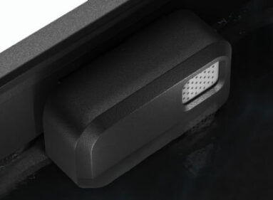
Setting the water level
Fill the Endoscopic LumbarBox Extended base unit with water up to the water sensor panel shown here.
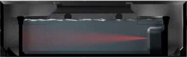
The sensor sounds an alarm if the water inside the base reaches a too high level.
Downloads
You can print this page for a hard copy version.
For further information on the Endoscopic LumbarBox extended please refer to the attached datasheet.
Was this article helpful?
We’re sorry to hear that.
Please can you give us some feedback to improve this page?
If you’d like a member of our support team to get back to you, please send a message to support@inovus.org